
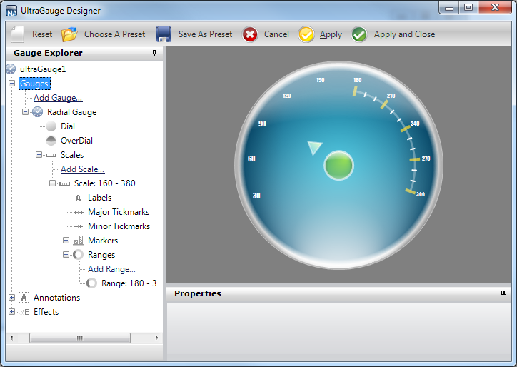
This procedure guides you through the process of creating a Radial gauge and setting the Dial, Scale and Label properties.
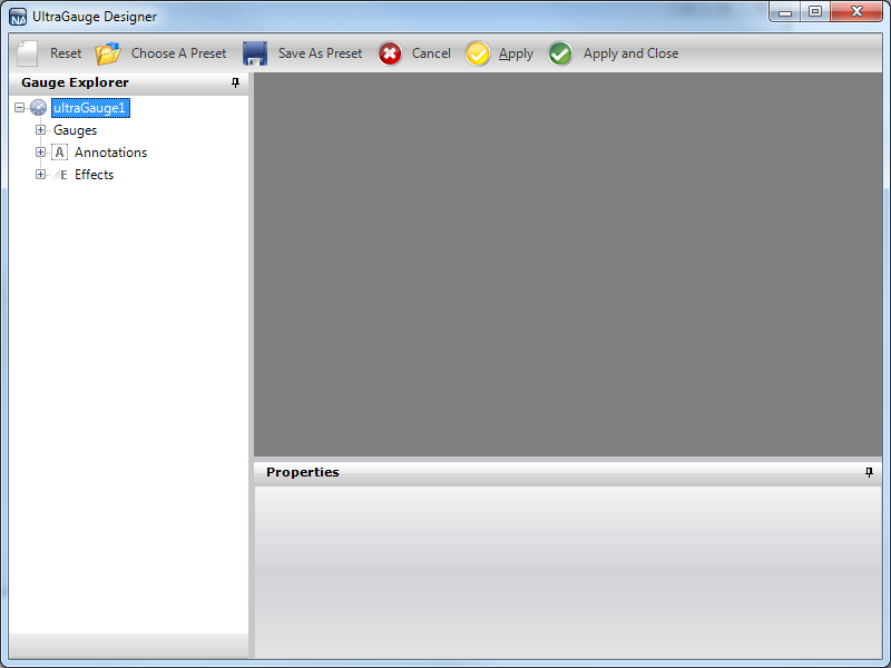
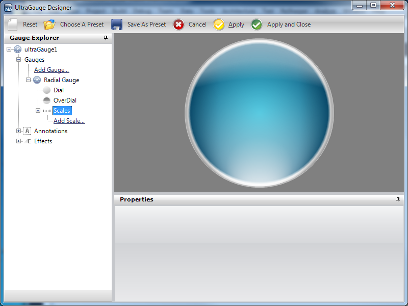
From the toolbox, drag the UltraGauge control to your form. The Gauge Designer opens.
In the Gauge Explorer, expand Gauges.
Click Add Gauge… and select New Radial Gauge.
Expand Radial Gauge and select OverDial.
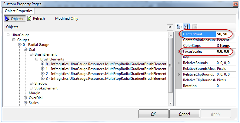
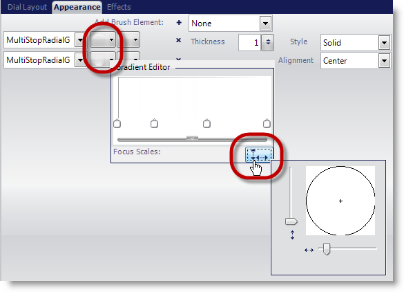
Before you continue with this step, please review the following note and screenshots to know how to assign the FocusScales and CenterPoint properties.
In the Properties panel, click the Appearance tab. In the Brush pane, add the following brush elements with the specified properties:
Multi-Stop Radial Gradient brush element
ColorStop 1 — Offset = 0, Color = Transparent
ColorStop 2 — Offset = 0.005045409, Color = Color.FromArgb(150, 255, 255, 255)
ColorStop 3 — Offset = 0.1413793, Color = Color.FromArgb(100, 255, 255, 255)
ColorStop 4 — Offset = 0.2689655, Color = Transparent
ColorStop 5 — Offset = 1, Color = Transparent
FocusScales — 3, 0
CenterPoint — 50, 100
Multi-Stop Radial Gradient brush element
ColorStop 1 — Offset = 0, Color = Transparent
ColorStop 2 — Offset = 0.2517241, Color = Color.FromArgb(46, 254, 254, 254)
ColorStop 3 — Offset = 0.6034483, Color = Color.FromArgb(120, 255, 255, 255)
ColorStop 4 — Offset = 1, Color = Color.FromArgb(255, 255, 255, 255)
FocusScales — 0.099999, 0
CenterPoint — 50, 110
Expand Radial Gauge and select Dial.
In the Properties panel, click the Appearance tab. In the Brush pane, add the following brush elements with the specified properties:
Multi-Stop Radial Gradient brush element
ColorStop 1 — Offset = 0, Color = Color.FromArgb(240, 240, 240)
ColorStop 2 — Offset = 0.4758621, Color = Color.FromArgb(210, 210, 210)
ColorStop 3 — Offset = 1, Color = Color.FromArgb(89, 89, 89)
FocusScales — 0.800000012, 0.800000012
CenterPoint — 50, 50
Multi-Stop Radial Gradient brush element
ColorStop 1 — Offset = 0, Color = Transparent
ColorStop 2 — Offset = 0.003548387, Color = Color.FromArgb(180, 180, 180)
ColorStop 3 — Offset = 0.04193548, Color = Color.FromArgb(240, 240, 240)
ColorStop 4 — Offset = 0.05870968, Color = Color.FromArgb(0, 79, 118)
ColorStop 5 — Offset = 1, Color = Color.FromArgb(0, 174, 209)
FocusScales — 0, 0
CenterPoint — 50, 50
Multi-Stop Radial Gradient brush element
ColorStop 1 — Offset = 0, Color = Transparent
ColorStop 2 — Offset = 0.02413793, Color = Color.FromArgb(40, 0, 0, 0)
ColorStop 3 — Offset = 0.2655172, Color = Color.FromArgb(30, 0, 0, 0)
ColorStop 4 — Offset = 0.4551724, Color = Transparent
ColorStop 5 — Offset = 1, Color = Transparent
FocusScales — 0.5, 3
CenterPoint — 100, 50
Multi-Stop Radial Gradient brush element
ColorStop 1 — Offset = 0, Color = Transparent
ColorStop 2 — Offset = 0.02413793, Color = Color.FromArgb(40, 0, 0, 0)
ColorStop 3 — Offset = 0.2655172, Color = Color.FromArgb(30, 0, 0, 0)
ColorStop 4 — Offset = 0.4551724, Color = Transparent
ColorStop 5 — Offset = 1, Color = Transparent
FocusScales — 0.5, 3
CenterPoint — 0,50
In the Stroke pane of the Appearance tab set the following properties:
Type — Solid
Details — Silver
Style — Solid
Thickness — 1
Alignment — Center
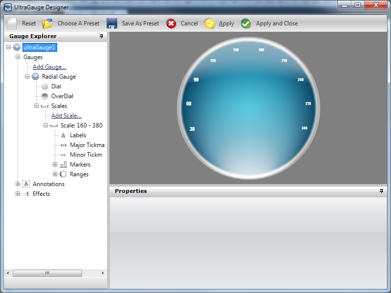
In the Gauge Explorer, expand Scales.
Click Add Scale… and select New Scale.
In the Properties panel, click the Scale Layout tab. In the Sweep Angle pane, set the following properties:
Start — 160
End — 380
In the Axis pane of the Scale Layout tab, set the following properties:
End Value — 300.00
Start Value — 30.00
Tickmark Interval — 1.0
In the Gauge Explorer, expand the newly created scale, and select Labels.
In the Properties panel, click the Labels Layout tab. In the Orientation pane, set the following properties:
Extent — 84
Orientation — Horizontal
In the Formatting pane of the Labels Layout tab, set the following properties:
Frequency — 30.00
Span Max — 10
Click the Labels Appearance tab. In the Brush pane set the following properties:
Type — Solid
Color — White
In the Font pane of the Labels Appearance tab, set the following properties:
Font — Impact
Font size — 14Type — Point
In the Gauge Explorer, select Major Tickmarks.
In the Properties panel, click the Tickmark Layout tab. In the Extent pane set the following properties:
Start — 68
End — 78
In the Widths pane of the Tickmark Layout tab, set the following properties:
Start — 4
End — 4
In the Orientation pane of the Tickmark Layout tab, set the following properties:
Frequency — 30.00
Post-Initial — 150
Click the Appearance tab. In the Brush pane, set the following properties:
Type — Solid
Color — Color.FromArgb(180, 255, 216, 22)
In the Stroke pane of the Appearance tab, set the following properties:
Type — Solid
Color — Color.FromArgb(232, 154, 0)
In the Gauge Explorer, select Minor Tickmarks.
In the Properties Panel, click the Tickmark Layout tab. In the Extent pane, set the following properties:
Start — 70
End — 75
In the Widths pane of the Tickmark Layout tab, set the following properties:
Start — 2
End — 2
In the Orientation pane of the Tickmark Layout tab, set the following properties:
Post-Initial — 150
Frequency — 10.00
Click the Appearance tab. In the Brush pane, set the following properties:
Type — Solid
Color — Color.FromArgb(0, 255, 255, 255)
In the Stroke pane of the Appearance tab, set the following properties:
Type — Solid
Color — White
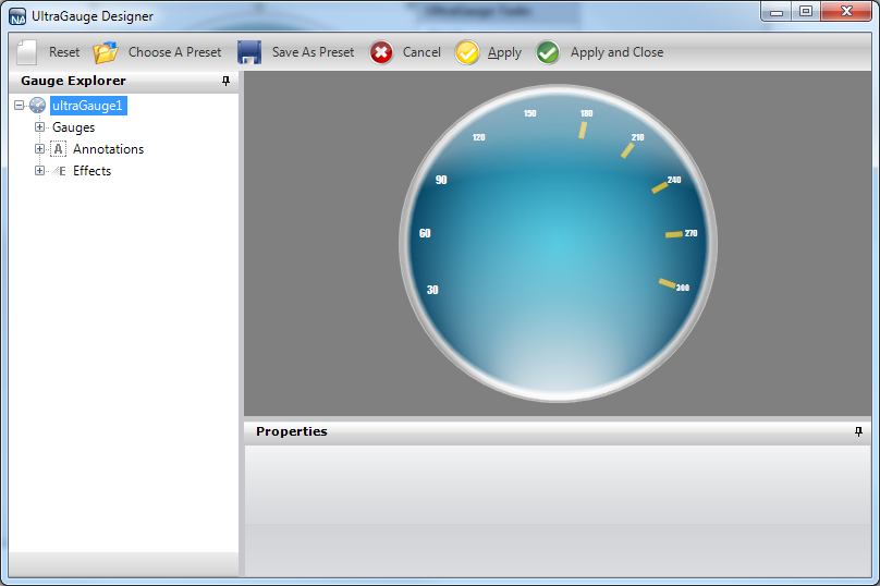
In the Gauge Explorer, expand Markers.
Click Add Marker… and select New Needle.
In the Properties Panel, click the Needle Marker Layout tab. In the Widths and Extents pane, set the following properties:
Widths
Start — 7
Mid — 7
End — 0
Extents
Start — -26
Mid — 26
End — 37
In the Value and Units pane of the Needle Marker Layout tab, set the following properties:
Value — 100.00
Precision — 100.00
Units — Percent
Click the Appearance tab. In the Brush pane, add the following brush elements with the specified properties:
Simple Gradient brush element
StartColor — Color = Color.FromArgb(230, 255, 181)
EndColor — Color = Color.FromArgb(180, 69, 209, 0)
Gradient Style — BackwardDiagonal
In the Stroke pane of the Appearance tab, set the following properties:
Type — Solid
Color — Color.FromArgb(125, 255, 255, 255)
Thickness — 2
In the Gauge Explorer, expand the newly created needle marker, and select Anchor.
In the Radius pane of the Anchor Layout tab, set the following property:
Value — 20
In the Properties panel, click the Appearance tab. In the Brush pane, add the following brush elements with the specified properties:
Multi-Stop Radial Gradient brush element
ColorStop 1 — Offset = 0, Color = Color.FromArgb(0, 141, 47)
ColorStop 2 — Offset = 1, Color = Color.FromArgb(104, 209, 0)
FocusScales — 0, 0
CenterPoint — 75, 25
Multi-Stop Radial Gradient brush element
ColorStop 1 — Offset = 0, Color = Transparent
ColorStop 2 — Offset = 0.02901786, Color = Color.FromArgb(80, 0, 0, 0)
ColorStop 3 — Offset = 0.1241379, Color = Transparent
ColorStop 4 — Offset = 1, Color = Transparent
FocusScales — 0, 3
CenterPoint — 100, 50
Multi-Stop Radial Gradient brush element
ColorStop 1 — Offset = 0, Color = Transparent
ColorStop 2 — Offset = 0.02901786, Color = Color.FromArgb(80, 0, 0, 0)
ColorStop 3 — Offset = 0.1241379, Color = Transparent
ColorStop 4 — Offset = 1, Color = Transparent
FocusScales — 0, 3
CenterPoint — 0, 50
Multi-Stop Radial Gradient brush element
ColorStop 1 — Offset = 0, Color = Transparent
ColorStop 2 — Offset = 0.02758621, Color = Color.FromArgb(200, 255, 255, 255)
ColorStop 3 — Offset = 0.3034483, Color = Color.FromArgb(0, 0, 0, 0)
ColorStop 4 — Offset = 0.3724138, Color = Transparent
ColorStop 5 — Offset = 1, Color = Transparent
FocusScales — 3, 0
CenterPoint — 50, 100
Multi-Stop Radial Gradient brush element
ColorStop 1 — Offset = 0, Color = Transparent
ColorStop 2 — Offset = 0.03103448, Color = Color.FromArgb(71, 255, 255, 255)
ColorStop 3 — Offset = 0.162069, Color = Transparent
ColorStop 4 — Offset = 0.3724138, Color = Transparent
ColorStop 5 — Offset = 1, Color = Transparent
FocusScales — 5, 0
CenterPoint — 50, 0
In the Stroke pane of the Appearance tab, set the following properties:
Radial Gradient brush element
SurroundColor — Color.FromArgb(180, 255, 255, 255)
CenterColor — Color.FromArgb(150, 255, 255, 255)
FocusScale — 0,0
CenterPoint — 75, 25
Thickness — 3
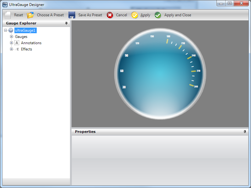
In the Gauge Explorer, expand Ranges.
Click Add Range… and select New Range.
In the Value pane of the Range Layout tab, set the following properties:
Start — 180.00
End — 300.00
In the Extent pane of the Range Layout tab, set the following properties:
Inner Start — 72
Inner End — 72
Outer — 74
In the Properties panel, click the Appearance tab. In the Brush pane, set the following properties:
Type — Solid
Color — Color.FromArgb(80, 255, 255, 255)
Thickness — 1
Related Topic