The purpose of this document is to show how the relationship types can be set for the connected nodes with icons indicating the source and target of the connected nodes within the xamNetworkNode™.
The table below maps the configurable visual representation of the source and target nodes relationship, the style and size of the corresponding icons.
The source indicates where the line initiates and the target indicates the line destination. The source is initiated from a parent node pointing to a child node as the target.
The table below maps the setting for visual representation of the source and target nodes relationship.
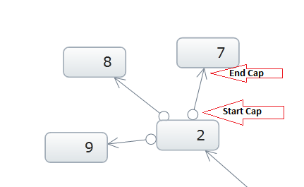
The image and code example below demonstrate the setting for LineStartCap/LineEndCap. Source node with the LineStartCap related to the target node with the LineEndCap:

In XAML:
<ig:XamNetworkNode LineStartCap="Ellipse" LineEndCap="Arrow">
In C#:
xnn.LineEndCap = LineCap.Arrow;
xnn.LineStartCap = LineCap.Ellipse;
In Visual Basic:
xnn.LineEndCap = LineCap.Arrow
xnn.LineStartCap = LineCap.Ellipse
The table below maps the setting of the style for corresponding icons for connecting nodes.
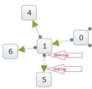
The image and code example bellow demonstrate the setting for LineStartCapStyle/LineEndCapStyle:

In XAML:
<Style TargetType="Path" x:Key="startCap">
     <Setter Property="Stroke" Value="DarkGreen" />
     <Setter Property="StrokeThickness" Value="1" />
     <Setter Property="Fill" Value="Gold" />
</Style>
<Style TargetType="Path" x:Key="endCap">
      <Setter Property="Stroke" Value="Red" />
      <Setter Property="Fill" Value="Goldenrod" />
      <Setter Property="StrokeThickness" Value="1" />
</Style>
The table below maps the setting of the size for corresponding icons for connecting nodes.
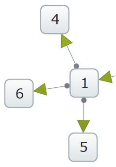
The image and code example bellow demonstrate the setting for LineStartCapSize/LineEndCapSize:

In XAML:
<ig:XamNetworkNode LineEndCapSize="15" LineStartCapSize="5">
In C#:
xnn.LineEndCapSize = 15;
xnn.LineStartCapSize = 5;
In Visual Basic:
xnn.LineEndCapSize = 15
xnn.LineStartCapSize = 5