
Creating a Radial gauge using the Gauge Designer:
allows you to save your gauge as a preset and use it for future applications
allows you to see your gauge as it is being created in the interactive preview area
simplifies the process of editing the properties on your gauge
Using the Gauge Designer to create a basic Radial gauge will help you understand the fundamentals of the Gauge Designer.
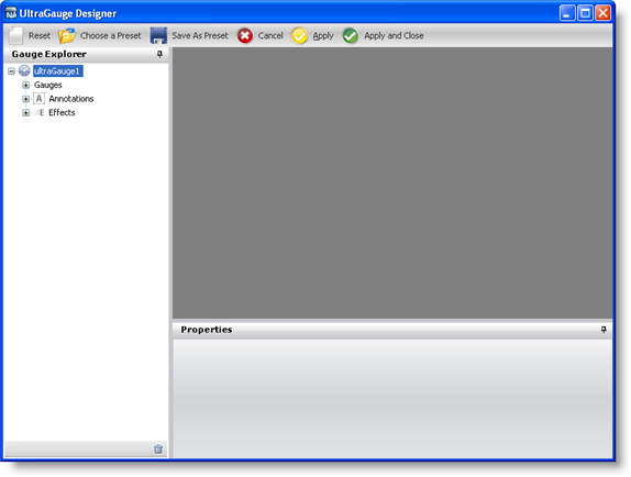
From the toolbox, drag the UltraGauge control to your form. The Gauge Designer opens.
In the Gauge Explorer, expand Gauges.
Click Add Gauge… and select New Radial Gauge.
Expand Radial Gauge and select Dial.
In the Properties panel, click the Appearance tab. In the Brush pane, add the following brush elements with the specified properties:
Multi-Stop Radial Gradient brush element
start color — 161, 161, 161
color stop — 96, 96, 96
color stop offset — 0.4758621
end color — 89, 89, 89
color — Gray
Multi-Stop Radial Gradient brush element
start color — Transparent
color stop — 141, 141, 141
color stop offset — 0.06206897
color stop — 82, 82, 82
color stop offset — 0.07586207
color stop — 45, 45, 45
color stop offset — 0.1448276
color stop — 30, 30, 30
color stop offset — 0.2448276
end color — 60, 60, 60
In the Stroke pane of the Appearance tab set the following properties:
Type — Solid
Details — Silver
Style — Solid
Thickness — 1
Alignment — Center
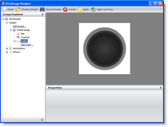
In the Gauge Explorer, expand Scales.
Click Add Scale… and select New Scale.
In Properties panel, click the Scale Layout tab. In the Sweep Angle pane, set the following properties:
Start — 135
End — 405
Click the Axis pane of the Scale Layout tab and set the End Value to 100.00\.
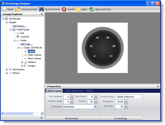
In the Gauge Explorer, expand the newly created scale, and select Labels.
In the Properties panel, click the Labels Layout tab. In the Orientation pane, set the following properties:
Extent — 55
Orientation — Outward
Click the Formatting pane of the Labels Layout tab and set the following properties:
Frequency — 20.00
Span Max — 18
Click the Labels Appearance tab. In the Brush pane set the following properties:
Type — Solid
Color — White
Click the Font pane of the Labels Appearance tab, and set the following properties:
Font size — 12
Type — Pixel
Style — Bold
In the Gauge Explorer, select Major Tickmarks.
In the Properties panel, click the Tickmark Layout tab. In the Extent pane set the following properties:
Start — 67
End — 79
Click the Widths pane of the Tickmark Layout tab, and set the following properties:
Start — 3
End — 3
Click the Orientation pane of the Tickmark Layout tab, and set the following property:
Frequency — 10.00
Click the Appearance tab. In the Brush pane, set the following properties:
Type — Solid
Color — 189, 189, 189
In the Gauge Explorer, select Minor Tickmarks.
In the Properties Panel, click the Tickmark Layout tab. In the Extent pane, set the following properties:
Start — 73
End — 78
In the Widths pane of the Tickmark Layout tab, set the following properties:
Start — 1
End — 1
In the Orientation pane of the Tickmark Layout tab, set the following property:
Frequency — 2.00
Click the Appearance tab. In the Brush pane, set the following properties:
Type — Solid
Color — 240, 240, 240
In the Stroke pane of the Appearance tab, set the following properties:
Type — Solid
Color — 135, 135, 135
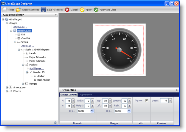
In the Gauge Explorer, expand Markers.
Click Add Marker… and select New Needle.
In the Properties Panel, click the Needle Marker Layout tab. In the Widths and Extents pane, set the following properties:
Widths
Start — 3
Mid — 3
End — 1
Extents
Start — -20
Mid — 0
End — 65
In the Value and Units pane of the Needle Marker Layout tab, set the following properties:
Value — 95.00
Precision — 1.00
Units — Percent
Click the Appearance tab. In the Brush pane, set the following properties:
Type — Solid
Color — 255, 61, 22
In the Gauge Explorer, expand the newly created needle marker, and select Anchor.
In the Properties panel, click the Appearance tab. In the Brush pane, set the following properties:
Type — SimpleGradient
Start Color — Gainsboro
End Color — 64, 64, 64
Gradient Style — BackwardDiagonal
In the Stroke pane of the Appearance tab, set the following properties:
Type — RadialGradient
SurroundColor — Gray
CenterColor — WhiteSmoke
FocusScale — 0,0
CenterPoint — 75, 25
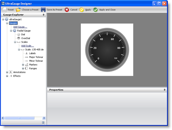
You have now successfully created a basic Radial gauge using the Gauge Designer. Your gauge should look like the gauge in the following screen shot.